What is RF Signal ?
A Radio Frequency signal is an electromagnetic wave that carries information over the air from one point to another.
RF signals starts as an electrical Alternating Current (AC), generated by a transmitter. This AC signal travels through the copper conductor and radiates out of an antenna in the form of electromagnetic wave.
What we see in the below diagram, is how a room would look if we were to have lot of devices emitting RF signals. These are waveforms commonly known as Sine Wave.
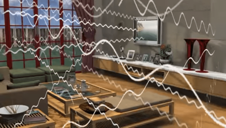
Just take a small portion of these RF signals and bifurcate it into 4 major variables,
a) Frequency
b) Wavelength
c) Amplitude
d) Phase

RF Spectrum ranges from 3 KHz to 300 GHz.
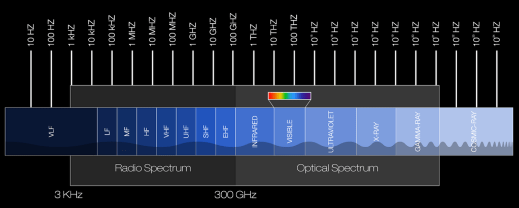
| # | BAND | FREQUENCY | WAVELENGTH |
| 1 | VLF – Very Low Frequency | 3 KHz – 30 KHz | 100 km – 10 km |
| 2 | LF – Low Frequency | 30 KHz – 300 KHz | 10 km – 1 km |
| 3 | MF – Medium Frequency | 300 KHz – 3 MHz | 1 km – 100 m |
| 4 | HF – High Frequency | 3 MHz – 30 MHz | 100 m – 10 m |
| 5 | VHF – Very High Frequency | 30 MHz – 300 MHz | 10 m – 1 m |
| 6 | UHF – Ultra High Frequency | 300 MHz – 3 GHz | 1 m – 100 mm |
| 7 | SHF – Super High Frequency | 3 GHz – 30 GHz | 100 mm – 10 mm |
| 8 | EHF – Extremely High Frequency | 30 GHz – 300 GHz | 10 mm – 1 mm |
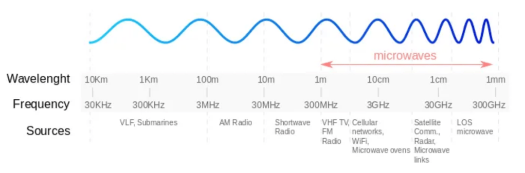
Below diagram would clearly show us how the wave pattern looks with respect to the distance it travels over the air.
References:
CWNA Official Study Guide
https://www.nasa.gov/
https://yatebts.com/
What is RF Signal ?
A Radio Frequency signal is an electromagnetic wave that carries information over the air from one point to another.
RF signals starts as an electrical Alternating Current (AC), generated by a transmitter. This AC signal travels through the copper conductor and radiates out of an antenna in the form of electromagnetic wave.
What we see in the below diagram, is how a room would look if we were to have lot of devices emitting RF signals. These are waveforms commonly known as Sine Wave.
Just take a small portion of these RF signals and bifurcate it into 4 major variables,
a) Frequency
b) Wavelength
c) Amplitude
d) Phase
RF Spectrum ranges from 3 KHz to 300 GHz.
| # | BAND | FREQUENCY | WAVELENGTH |
| 1 | VLF – Very Low Frequency | 3 KHz – 30 KHz | 100 km – 10 km |
| 2 | LF – Low Frequency | 30 KHz – 300 KHz | 10 km – 1 km |
| 3 | MF – Medium Frequency | 300 KHz – 3 MHz | 1 km – 100 m |
| 4 | HF – High Frequency | 3 MHz – 30 MHz | 100 m – 10 m |
| 5 | VHF – Very High Frequency | 30 MHz – 300 MHz | 10 m – 1 m |
| 6 | UHF – Ultra High Frequency | 300 MHz – 3 GHz | 1 m – 100 mm |
| 7 | SHF – Super High Frequency | 3 GHz – 30 GHz | 100 mm – 10 mm |
| 8 | EHF – Extremely High Frequency | 30 GHz – 300 GHz | 10 mm – 1 mm |
Below diagram would clearly show us how the wave pattern looks with respect to the distance it travels over the air.
References:
CWNA Official Study Guide
https://www.nasa.gov/
https://yatebts.com/
